

Shell and tube heat exchangers are among the most versatile and widely used heat exchange systems in industries worldwide. These heat exchangers operate on the principle of transferring heat between two fluids—one flowing inside the tubes and the other outside the tubes within a shell—without mixing them. Their robust design allows them to withstand high pressure and extreme temperatures, making them a preferred choice in power plants, chemical processing, oil and gas refineries, HVAC systems, and food production industries.
Their popularity stems from their ability to efficiently transfer heat in a compact space while maintaining durability and ease of maintenance. They come in various configurations, including fixed tube sheets, U-tube, floating head, and kettle reboilers, each designed to cater to specific industrial requirements. The adaptability of shell and tube heat exchangers to different types of fluids, including corrosive and high-viscosity liquids, enhances their utility in specialized applications.
Components of Shell and Tube Heat Exchangers
- Shell
- The shell is the outer casing that encloses the tube bundle and facilitates the flow of the shell-side fluid.
- It is typically constructed from strong materials like carbon steel or stainless steel to withstand pressure and corrosion.
- The size and design of the shell determine the heat exchanger’s capacity and efficiency.
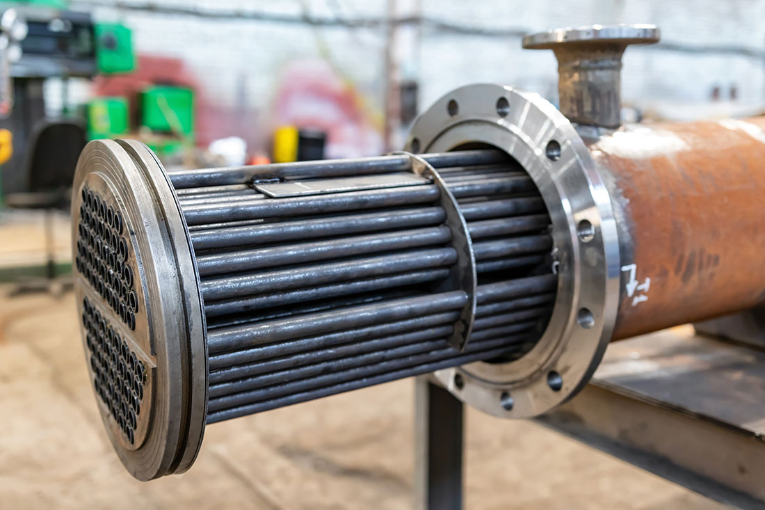
- Tube Bundle
- The tube bundle consists of multiple small-diameter tubes through which the tube-side fluid flows.
- It includes various configurations, such as straight tubes or U-tubes, depending on the design requirements.
- The material of the tubes is chosen based on the thermal conductivity, corrosion resistance, and pressure handling capacity needed for the application.
- Tube Sheet
- Tube sheets are perforated plates that hold the tubes in place at both ends of the exchanger.
- They serve as structural components and also help prevent leaks between the shell and tube-side fluids.
- They can be fixed or floating, depending on the type of heat exchanger.
- Baffles
- Baffles are metal plates positioned inside the shell to direct the flow of the shell-side fluid.
- They create turbulence, which increases heat transfer efficiency by ensuring uniform fluid distribution and reducing the formation of stagnant zones.
- Baffles also provide mechanical support to the tubes, preventing vibration and damage due to flow-induced forces.
- Front Header (Stationary Head)
- This is the section where the tube-side fluid enters the exchanger.
- It can be designed for single-pass or multi-pass configurations, depending on the required heat exchange efficiency.
- The front header is usually bolted to allow for easy maintenance and cleaning.
Working Principle
Shell and tube heat exchangers operate based on the principle of heat transfer through conduction. The working fluid inside the tubes absorbs or releases heat to the shell-side fluid as they pass through the exchanger. The efficiency of heat transfer depends on several factors, including flow arrangement, temperature gradient, and turbulence level.
- Parallel Flow – Both fluids enter the heat exchanger at the same end and move in the same direction. This method is less efficient because the temperature difference between the fluids decreases along the length of the exchanger.
- Counterflow – Fluids enter from opposite ends, maintaining a higher temperature gradient throughout the exchanger, which maximizes heat transfer efficiency.
- Crossflow – Fluids move perpendicular to each other, commonly used in applications requiring moderate heat exchange efficiency.
Types of Shell and Tube Heat Exchangers
- Fixed Tube Sheet Heat Exchanger
- The tube bundle is permanently attached to the shell, making it simple and cost-effective.
- Cleaning and maintenance are easier on the tube side but difficult on the shell side.
- Suitable for applications with minimal temperature variations to prevent thermal expansion issues.
- U-Tube Heat Exchanger
- The tubes are bent into a U-shape, allowing for expansion and contraction due to temperature changes.
- The tube bundle can be removed for easy maintenance and cleaning.
- Well-suited for high-temperature applications where thermal stress is a concern.
- Floating Head Heat Exchanger
- One end of the tube bundle is free to move, allowing for thermal expansion.
- Both the shell and tube sides can be cleaned, making it ideal for applications with dirty fluids.
- Commonly used in petrochemical and power plant applications.
- Kettle Reboiler Heat Exchanger
- Used in distillation and chemical processing industries to vaporize liquids.
- The shell side has a large volume to accommodate phase change and maintain heat balance.
- Provides a stable heat source for fractionation processes.
- Double-Pass or Multi-Pass Heat Exchanger
- The tube-side fluid passes multiple times through the exchanger to enhance heat transfer.
- Designed for applications where space constraints require a more compact yet efficient solution.
Shell and tube heat exchangers are fundamental components in industrial heat management, offering durability, efficiency, and adaptability. Their ability to handle extreme conditions while maintaining high thermal performance makes them indispensable in industries ranging from power generation to pharmaceuticals. With continuous advancements in materials and design, shell and tube heat exchangers are becoming more efficient, compact, and environmentally friendly, playing a crucial role in energy conservation and process optimization.