

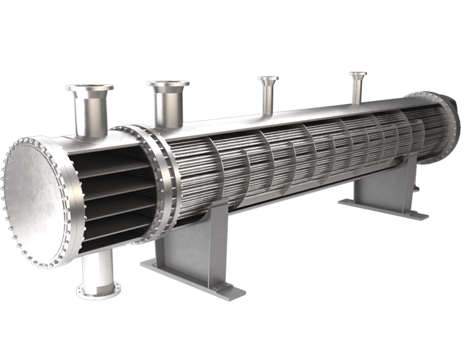
A shell and tube heat exchanger is a popular class of heat exchanger designs. It consists of a number of tubes mounted inside a cylindrical shell. One fluid flows inside the tubes and the other through the shell. While flowing they exchange the heats where the cold fluid gains the heat from the hot fluid. So, one cold fluid enters the shell (or tube side or channel side) inlet nozzle and comes out of the outlet nozzle as hot fluid. Consequently, other fluid will become cold in the outlet than in the inlet. The fluid flow inside the shell and tube heat exchanger can be parallel flow or crossflow.
The simple design of a shell and tube heat exchanger makes it an ideal cooling solution for a wide variety of applications.
One of the most common applications is the cooling of hydraulic fluid and oil in engines, transmissions and hydraulic power packs. With the right choice of materials, they can also be used to cool or heat other mediums, such as swimming pool water or charge air. There are many advantages to shell and tube technology. One of the big advantages of using a shell and tube heat exchanger is that they are often easy to service. It is particularly favourable in applications where the cold medium is charged with particles or prone to fouling and the maintenance of heat exchangers with shell and tube technology is quick and efficient compared to other technologies.
Also, the cylindrical design of the housing is extremely resistant to pressure and allows all ranges of pressure applications.
The design and choice of the types and dimensions of the STHX components for this project was done following the standards presented by the Tubular Exchanger Manufacturing Association (TEMA).
Dubai, Abu Dhabi, Sharjah, Al Ain, Ajman, Ras Al Khaimah, Fujairah, Umm Al Quwain, Khor Fakkan, Kalba, Ras Al Khor, Al Quoz, Al Safa, Al Khubaisi, jebel Ali,
Heat exchanger in United Arab Emirates
We are Manufacturer and supplier of Heat Exchanger in UAE. We are one of the leading manufactures of Heat Exchanger
Shell & Tube Heat Exchangers The Fundamentals
At its core, a shell & tube heat exchanger is comprised of numerous tubes housed within a larger cylindrical shell. This design facilitates the efficient exchange of heat as one fluid flows inside the tubes while another fluid flows outside the tubes within the shell. The design is versatile and can cater to a wide range of processes, temperatures, and pressures.
Construction Elements
The design of shell & tube heat exchangers includes several key components:
Channels
Channels in heat exchangers serve as entry and exit points for the tube-side fluids. They are designed to ensure uniform distribution of the fluid through the tube bundle to maximize heat transfer efficiency. Pass-partition plates are used to direct and separate flows between each tube-side pass.
Tubes
Tubes are the primary surface through which heat is exchanged. Materials like carbon steel, stainless steel, duplex, and high-nickel alloys (Inconel, Hasteloy) are often used, typically selected based on factors like resistance to corrosion, temperature suitability, and overall cost . Low-finned tubes and other enhancements are available to increase the heat transfer coefficient as needed in certain services. Tube internals like twisted tape and wire inserts are also available and best used when exchanger performance or cost can be improved upon.
Tube Sheet
The tubesheet is a critical component that holds (fixes) the tubes in place, sealing and supporting them at the ends. Tubes are often attached to the tubesheet(s) via mechanical means using two-ring-grooves machined into the tubesheet holes, and then hydraulically (or pneumatically) expanding the tube into the tubesheet and grooves (aka, 2RG & Expanded). Another common method is via a welded joint, typically considered a two-pass strength weld. Single-pass seal-welds are sometimes added to expanded joints to minimize the risk of one process stream leaking into the other.
Tube Pitch and Layout
Tube pitch and layout is crucial, as it affects the overall heat transfer and pressure drop. Tube pitch is the distance between adjacent tubes (often 1.25x tube OD), and tube layout is the arrangement of the tubes relative to shell-side baffle flow, either triangular (30° or 60°), square (90°), or rotated square (45°). Triangular layouts are cost effective and maximize performance relative to cost, but are more difficult to clean in shell-side services with heavy fouling. Square pitch allows for shell-side mechanical cleaning, but generally is the most costly layout. Rotated square layouts have some of the performance benefits of a triangular pitch, but with the accessibility of a square pitch. Tube pitch is often adjusted to balance heat transfer efficiency and pressure drop within the heat exchanger.
Shell
The shell is the pressure envelope of the heat exchanger. It contains the fluid that flows over (outside) the tubes. The shell’s configuration, including its diameter and length, is mostly a function of the bundle design.
Tie Rods and Spacers
Tie rods and spacers maintain the tube bundle’s alignment and support the baffle structure (aka, skeleton). They play a vital role in ensuring the structural integrity of the heat exchanger, but do not contribute to heat transfer.
Baffles
Baffles direct the shell-side fluid across the tube bundle, enhancing the heat transfer coefficient. They also help in supporting the tubes, preventing damaging vibration and wear. Single-segmental baffles are the most common, easily directing flow back and forth across the tubes. They can be cut and oriented so that shell-side flow is going side to side or up and down. When shell-side pressure drop (and velocities) are too high, double-segmental baffles can be used to reduce them both. Double-segmental baffles are almost always cut in the vertical direction in order to provide proper tube support. Helical baffles via a licensed technology like Lummus Helix changers can be used to leverage the available pressure drop, achieve higher shell-side performance, higher average velocities, reduced fouling, and reduced costs.