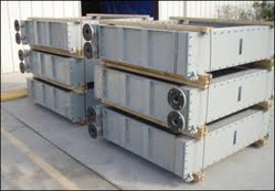
Generator Heat Exchanger
Overview:
Generator heat exchangers are understands the degradation of steam generator heat exchanger tubing, both mechanical and corrosion modes, which has resulted in extensive repairs and the replacements around the world. The variety of degradation modes challenges the integrity of tubing and, therefore, the stations’ reliability. Inspection and monitoring aimed at timely detection and characterization of the degradation is a key element for ensuring tube integrity. Generator heat exchangers incorporates the bobbin probe, primarily for volumetric indications such as pitting and fretting, and the X-probe which is a T/R (transmit/receive) array probe used for detection of axial or circumferential indications, along with volumetric indications.
Process:
Processes of Generator heat exchangers the temperature difference between the two surfaces of the thermoelectric module(s) generates electricity using the see beck Effect. When hot exhaust from the engine passes through an exhaust ATEG, the charge carriers of the semiconductors within the generator diffuse from the hot-side heat exchanger to the cold-side exchanger. The build-up of charge carriers results in a net charge, producing an electrostatic potential while the heat transfer drives a current. With exhaust temperatures of 700°C (~1300°F) or more, the temperature difference between exhaust gas on the hot side and coolant on the cold side is several hundred degrees. This temperature difference is capable of generating 500-750 W of electricity. The compression assembly system aims to decrease the thermal contact resistance between the thermoelectric module and the heat exchanger surfaces. In coolant-based ATEGs, the cold side heat exchanger uses engine coolant as the cooling fluid, while in exhaust-based ATEGs, the cold-side heat exchanger uses ambient air as the cooling fluid.
Generator Heat Exchangers:
- All 304 stainless steel construction.
- Up to 50,000 Btu/hr. heating capacity. Note that its the horsepower (load) the engine is operating under (not the engine rating) that determines the amount of heat available.
- Water or water/glycol are typical fluids for heating.
- 125 psig maximum fluid working pressure.
- Water pressure drops at various flow rates are
- 15 gpm 5 psi
- 10 gpm 2.0 psi
- 8 gpm 1.5 psi
- 5 gpm 0.5 psi
- The exhaust pressure drop is dependent on gas inlet temperature and water temperature. Typical pressure drop for an 18 hp engine is under 0.75 psi.
- Exhaust gas temperature will be within 100 F of the water exit temperature.
- Water inlet and outlet fittings are 1” NPT Female
- Overall dimensions are 18.0 long by 10.375 inches tall by 6.375 inches deep.
- Weight is 27 pounds dry.
- Shipping weight is 31 lbs. and container dimensions are 24” X 12” X 10”
Features:
- Precise functionality
- Superior cooling and heating
- No operation damage
- Low fuel consumption
- No space wasting
- Easy to install & maintain
- Corrosion resistant
- Leak proof structure
Advantages:
- Longer life cycle
- Massive output parameters coming out of small input parameters
- Quick response during the starting process
- Regulation on the output in the range from 0 to 100%
- Water heating on high temperatures (huge temperature differences)
Applications:
- Hydronic floor heating.
- Engine driven carpet, floor, and steam cleaners.
- Space heating.
- Eliminates wet exhaust systems for marine generators.
- Provides heat for absorption air-conditioners.
Image:


